Instrumentation
The Instrument API provide a consistent way of collecting measurements from
a target. Measurements are collected via an instance of a class derived from
Instrument. An Instrument allows collection of
measurement from one or more channels. An Instrument may support
INSTANTANEOUS or CONTINUOUS collection, or both.
Example
The following example shows how to use an instrument to read temperature from an Android target.
# import and instantiate the Target and the instrument
# (note: this assumes exactly one android target connected
#  to the host machine).
In [1]: from devlib import AndroidTarget, HwmonInstrument

In [2]: t = AndroidTarget()

In [3]: i = HwmonInstrument(t)

# Set up the instrument on the Target. In case of HWMON, this is
# a no-op, but is included here for completeness.
In [4]: i.setup()

# Find out what the instrument is capable collecting from the
# target.
In [5]: i.list_channels()
Out[5]:
[CHAN(battery/temp1, battery_temperature),
 CHAN(exynos-therm/temp1, exynos-therm_temperature)]

# Set up a new measurement session, and specify what is to be
# collected.
In [6]: i.reset(sites=['exynos-therm'])

# HWMON instrument supports INSTANTANEOUS collection, so invoking
# take_measurement() will return a list of measurements take from
# each of the channels configured during reset()
In [7]: i.take_measurement()
Out[7]: [exynos-therm_temperature: 36.0 degrees]
API
Instrument
-
class
devlib.instrument.Instrument(target, **kwargs)[source]¶ An
Instrumentallows collection of measurement from one or more channels. AnInstrumentmay supportINSTANTANEOUSorCONTINUOUScollection, or both.
-
Instrument.mode¶ A bit mask that indicates collection modes that are supported by this instrument. Possible values are:
INSTANTANEOUS: The instrument supports taking a single sample via take_measurement().CONTINUOUS: The instrument supports collecting measurements over a period of time via start(),stop(),get_data(), and (optionally)get_rawmethods.Note
It’s possible for one instrument to support more than a single mode.
-
Instrument.active_channels¶ Channels that have been activated via
reset(). Measurements will only be collected for these channels.
-
Instrument.list_channels()[source]¶ Returns a list of
InstrumentChannelinstances that describe what this instrument can measure on the current target. A channel is a combination of akindof measurement (power, temperature, etc) and asitethat indicates where on the target the measurement will be collected from.
-
Instrument.get_channels(measure)[source]¶ Returns channels for a particular
measuretype. Ameasurecan be either a string (e.g."power") or aMeasurmentTypeinstance.
-
Instrument.setup(*args, **kwargs)[source]¶ This will set up the instrument on the target. Parameters this method takes are particular to subclasses (see documentation for specific instruments below). What actions are performed by this method are also instrument-specific. Usually these will be things like installing executables, starting services, deploying assets, etc. Typically, this method needs to be invoked at most once per reboot of the target (unless
teardown()has been called), but see documentation for the instrument you’re interested in.
-
Instrument.reset(sites=None, kinds=None, channels=None)[source]¶ This is used to configure an instrument for collection. This must be invoked before
start()is called to begin collection. This methods sets theactive_channelsattribute of theInstrument.If
channelsis provided, it is a list of names of channels to enable andsitesandkindsmust both beNone.Otherwise, if one of
sitesorkindsis provided, all channels matching the given sites or kinds are enabled. If both are provided then all channels of the given kinds at the given sites are enabled.If none of
sites,kindsorchannelsare provided then all available channels are enabled.
-
Instrument.take_measurement()[source]¶ Take a single measurement from
active_channels. Returns a list ofMeasurementobjects (one for each active channel).Note
This method is only implemented by
Instruments that supportINSTANTANEOUSmeasurement.
-
Instrument.start()[source]¶ Starts collecting measurements from
active_channels.Note
This method is only implemented by
Instruments that supportCONTINUOUSmeasurement.
-
Instrument.stop()[source]¶ Stops collecting measurements from
active_channels. Must be called afterstart().Note
This method is only implemented by
Instruments that supportCONTINUOUSmeasurement.
-
Instrument.get_data(outfile)[source]¶ Write collected data into
outfile. Must be called afterstop(). Data will be written in CSV format with a column for each channel and a row for each sample. Column heading will be channel, labels in the form<site>_<kind>(seeInstrumentChannel). The order of the columns will be the same as the order of channels inInstrument.active_channels.If reporting timestamps, one channel must have a
sitenamed"timestamp"and akindof aMeasurmentTypeof an appropriate time unit which will be used, if appropriate, during any post processing.Note
Currently supported time units are seconds, milliseconds and microseconds, other units can also be used if an appropriate conversion is provided.
This returns a
MeasurementCsvinstance associated with the outfile that can be used to streamMeasurements lists (similar to what is returned bytake_measurement().Note
This method is only implemented by
Instruments that supportCONTINUOUSmeasurement.
-
Instrument.get_raw()[source]¶ - Returns a list of paths to files containing raw output from the underlying source(s) that is used to produce the data CSV. If no raw output is generated or saved, an empty list will be returned. The format of the contents of the raw files is entirely source-dependent.
Note
This method is not guaranteed to return valid filepaths after the
teardown()method has been invoked as the raw files may have been deleted. Please ensure that copies are created manually prior to callingteardown()if the files are to be retained.
-
Instrument.teardown()[source]¶ Performs any required clean up of the instrument. This usually includes removing temporary and raw files (if
keep_rawis set toFalseon relevant instruments), stopping services etc.
-
Instrument.sample_rate_hz¶ Sample rate of the instrument in Hz. Assumed to be the same for all channels.
Note
This attribute is only provided by
Instruments that supportCONTINUOUSmeasurement.
Instrument Channel
-
class
devlib.instrument.InstrumentChannel(name, site, measurement_type, **attrs)[source]¶ An
InstrumentChanneldescribes a single type of measurement that may be collected by anInstrument. A channel is primarily defined by asiteand ameasurement_type.A
siteindicates where on the target a measurement is collected from (e.g. a voltage rail or location of a sensor).A
measurement_typeis an instance ofMeasurmentTypethat describes what sort of measurement this is (power, temperature, etc). Each measurement type has a standard unit it is reported in, regardless of an instrument used to collect it.A channel (i.e. site/measurement_type combination) is unique per instrument, however there may be more than one channel associated with one site (e.g. for both voltage and power).
It should not be assumed that any site/measurement_type combination is valid. The list of available channels can queried with
Instrument.list_channels().
-
InstrumentChannel.site¶ The name of the “site” from which the measurements are collected (e.g. voltage rail, sensor, etc).
-
InstrumentChannel.kind¶ A string indicating the type of measurement that will be collected. This is the
nameof theMeasurmentTypeassociated with this channel.
-
InstrumentChannel.units¶ Units in which measurement will be reported. this is determined by the underlying
MeasurmentType.
-
InstrumentChannel.label¶ A label that can be attached to measurements associated with with channel. This is constructed with
'{}_{}'.format(self.site, self.kind)
Measurement Types
In order to make instruments easer to use, and to make it easier to swap them out when necessary (e.g. change method of collecting power), a number of standard measurement types are defined. This way, for example, power will always be reported as “power” in Watts, and never as “pwr” in milliWatts. Currently defined measurement types are
| name | units | category |
|---|---|---|
| count | count | |
| percent | percent | |
| time_us | microseconds | time |
| time_ms | milliseconds | time |
| temperature | degrees | thermal |
| power | watts | power/energy |
| voltage | volts | power/energy |
| current | amps | power/energy |
| energy | joules | power/energy |
| tx | bytes | data transfer |
| rx | bytes | data transfer |
| tx/rx | bytes | data transfer |
Available Instruments
This section lists instruments that are currently part of devlib.
Todo
Add other instruments
Baylibre ACME BeagleBone Black Cape
From the official project page:
[The Baylibre Another Cute Measurement Equipment (ACME)] is an extension for the BeagleBone Black (the ACME Cape), designed to provide multi-channel power and temperature measurements capabilities to the BeagleBone Black (BBB). It comes with power and temperature probes integrating a power switch (the ACME Probes), turning it into an advanced all-in-one power/temperature measurement solution.
The ACME initiative is completely open source, from HW to SW drivers and applications.
The Infrastructure
Retrieving measurement from the ACME through devlib requires:
- a BBB running the image built for using the ACME (micro SD card required);
- an ACME cape on top of the BBB;
- at least one ACME probe [1] connected to the ACME cape;
- a BBB-host interface (typically USB or Ethernet) [2];
- a host (the one running devlib) with libiio (the Linux IIO interface) installed, and a Python environment able to find the libiio Python wrapper i.e. able to
import iioas communications between the BBB and the host rely on the Linux Industrial I/O Subsystem (IIO).
The ACME probes are built on top of the Texas Instruments INA226 and the data acquisition chain is as follows:
![digraph target {
rankdir = LR
bgcolor = transparent
subgraph cluster_target {
subgraph cluster_BBB {
node [style = filled, color = white];
style = filled;
color = lightgrey;
label = "BeagleBone Black";
drivers -> "IIO Daemon" [dir = both]
}
subgraph cluster_INA226 {
node [style = filled, color = white];
style = filled;
color = lightgrey;
label = INA226;
ADC -> Processing
Processing -> Registers
}
subgraph cluster_inputs {
node [style = filled, color = white];
style = filled;
color = lightgrey;
label = Inputs;
"Bus Voltage" -> ADC;
"Shunt Voltage" -> ADC;
}
Registers -> drivers [dir = both, label = I2C];
}
subgraph cluster_IIO {
style = none
"IIO Daemon" -> "IIO Interface" [dir = both, label = "Eth./USB"]
}
}](_images/graphviz-59bb23140db02e6c59e30a0e333d8735b385bb3d.png)
For reference, the software stack on the host is roughly given by:
![digraph host {
rankdir = LR
bgcolor = transparent
subgraph cluster_host {
subgraph cluster_backend {
node [style = filled, color = white];
style = filled;
color = lightgrey;
label = Backend;
"IIO Daemon" -> "C API" [dir = both]
}
subgraph cluster_Python {
node [style = filled, color = white];
style = filled;
color = lightgrey;
label = Python;
"C API" -> "iio Wrapper" [dir = both]
"iio Wrapper" -> devlib [dir = both]
devlib -> "User" [dir = both]
}
}
subgraph cluster_IIO {
style = none
"IIO Interface" -> "IIO Daemon" [dir = both, label = "Eth./USB"]
}
}](_images/graphviz-a6dd2c9ef257c3c9a72f3734876b8d344cf3a4e5.png)
Ethernet was the only IIO Interface used and tested during the development of this instrument. However, USB seems to be supported. The IIO library also provides “Local” and “XML” connections but these are to be used when the IIO devices are directly connected to the host i.e. in our case, if we were to run Python and devlib on the BBB. These are also untested.
Measuring Power
In IIO terminology, the ACME cape is an IIO context and ACME probes are IIO devices with IIO channels. An input IIO channel (the ACME has no output IIO channel) is a stream of samples and an ACME cape can be connected to up to 8 probes i.e. have 8 IIO devices. The probes are discovered at startup by the IIO drivers on the BBB and are indexed according to the order in which they are connected to the ACME cape (with respect to the “Probe X” connectors on the cape).
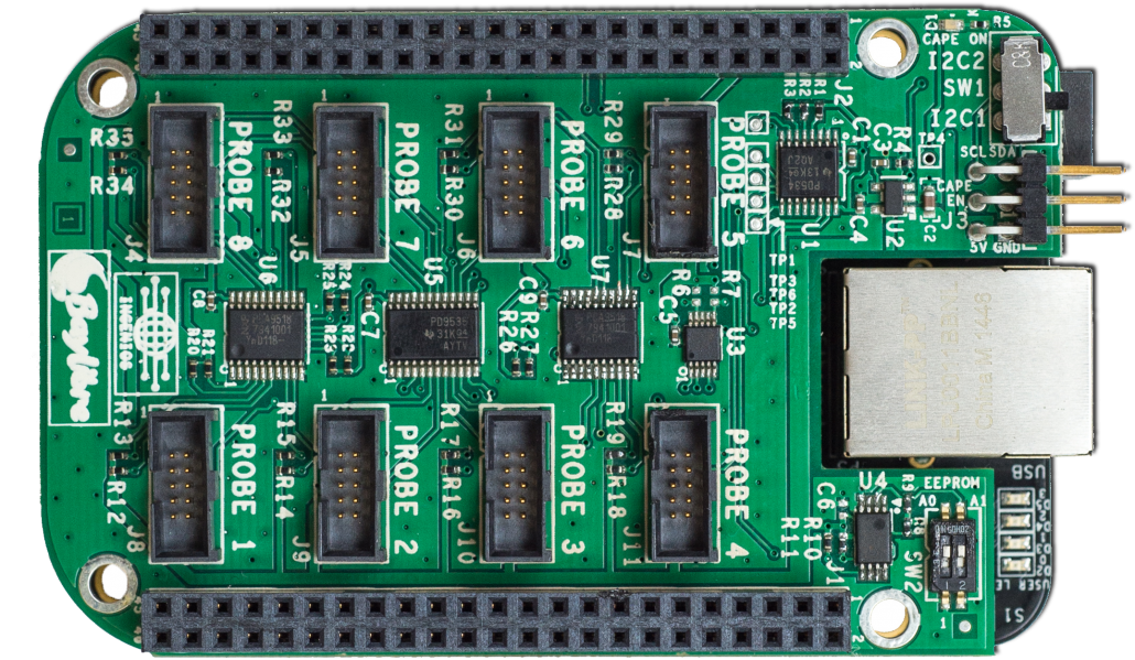
ACME Cape on top of a BBB: Notice the numbered probe connectors ( source)
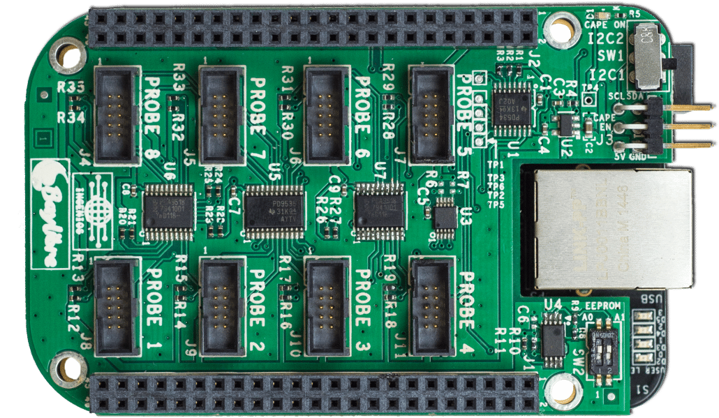
Please note that the numbers on the PCB do not represent the index of a probe
in IIO; on top of being 1-based (as opposed to IIO device indexing being
0-based), skipped connectors do not result in skipped indices e.g. if three
probes are connected to the cape at Probe 1, Probe 3 and Probe 7,
IIO (and therefore the entire software stack, including devlib) will still
refer to them as devices 0, 1 and 2, respectively. Furthermore,
probe “hot swapping” does not seem to be supported.
INA226: The probing spearhead
An ACME probe has 5 IIO channels, 4 of which being “IIO wrappers” around what the INA226 outputs (through its I2C registers): the bus voltage, the shunt voltage, the shunt current and the load power. The last channel gives the timestamps and is probably added further down the pipeline. A typical circuit configuration for the INA226 (useful when shunt-based ACME probes are used as their PCB does not contain the full circuit unlike the USB and jack variants) is given by its datasheet:
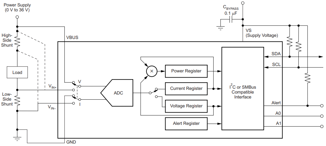
Typical Circuit Configuration (source: Texas Instruments INA226)
The analog-to-digital converter (ADC)
The digital time-discrete sampled signal of the analog time-continuous input voltage signal is obtained through an analog-to-digital converter (ADC). To measure the “instantaneous input voltage”, the ADC “charges up or down” a capacitor before measuring its charge.
The integration time is the time spend by the ADC acquiring the input signal in its capacitor. The longer this time is, the more resilient the sampling process is to unwanted noise. The drawback is that, if the integration time is increased then the sampling rate decreases. This effect can be somewhat compared to a low-pass filter.
As the INA226 alternatively connects its ADC to the bus voltage and shunt voltage (see previous figure), samples are retrieved at a frequency of
where \(T_X\) is the integration time for the \(X\) voltage.
As described below (BaylibreAcmeInstrument.reset), the
integration times for the bus and shunt voltage can be set separately which
allows a tradeoff of accuracy between signals. This is particularly useful as
the shunt voltage returned by the INA226 has a higher resolution than the bus
voltage (2.5 μV and 1.25 mV LSB, respectively) and therefore would benefit more
from a longer integration time.
As an illustration, consider the following sampled sine wave and notice how increasing the integration time (of the bus voltage in this case) “smoothes” out the signal:
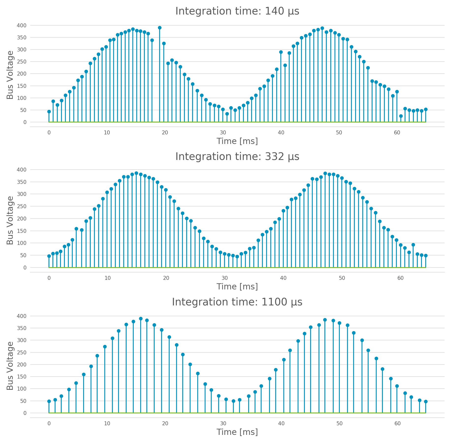
Increasing the integration time increases the resilience to noise
Internal signal processing
The INA226 is able to accumulate samples acquired by its ADC and output to the ACME board (technically, to its I2C registers) the average value of \(N\) samples. This is called oversampling. While the integration time somewhat behaves as an analog low-pass filter, the oversampling feature is a digital low-pass filter by definition. The former should be set to reduce sampling noise (i.e. noise on a single sample coming from the sampling process) while the latter should be used to filter out high-frequency noise present in the input signal and control the sampling frequency.
Therefore, samples are available at the output of the INA226 at a frequency
and oversampling ratio provides a way to control the output sampling frequency (i.e. to limit the required output bandwidth) while making sure the signal fidelity is as desired.
The 4 IIO channels coming from the INA226 can be grouped according to their respective origins: the bus and shunt voltages are measured (and, potentially filtered) while the shunt current and load power are computed. Indeed, the INA226 contains on-board fixed-point arithmetic units to compute the trivial expressions:
A functional block diagram of this is also given by the datasheet:
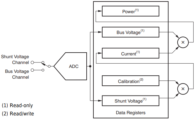
Acquisition and Processing: Functional Block Diagram (source: Texas Instruments INA226)
In the end, there are therefore 3 channels (bus voltage, shunt voltage and timestamps) that are necessary to figure out the load power consumption, while the others are being provided for convenience e.g. in case the rest of the hardware does not have the computing power to make the computation.
Sampling Frequency Issues
It looks like the INA226-ACME-BBB setup has a bottleneck preventing the sampling frequency to go higher than ~1.4 kHz (the maximal theoretical sampling frequency is ~3.6 kHz). We know that this issue is not internal to the ADC itself (inside of the INA226) because modifying the integration time affects the output signal even when the sampling frequency is capped (as shown above) but it may come from anywhere after that.
Because of this, there is no point in using a (theoretical) sampling frequency
that is larger than 1.4 kHz. But it is important to note that the ACME will
still report the theoretical sampling rate (probably computed with the formula
given above) through BaylibreAcmeInstrument.sample_rate_hz and
IIOINA226Instrument.sample_rate_hz even if it differs from the actual
sampling rate.
Note that, even though this is obvious for the theoretical sampling rate, the specific values of the bus and shunt integration times do not seem to have an influence on the measured sampling rate; only their sum matters. This further points toward a data-processing bottleneck rather than a hardware bug in the acquisition device.
The following chart compares the evolution of the measured sampling rate with the expected one as we modify it through \(T_{shunt}\), \(T_{bus}\) and \(N\):
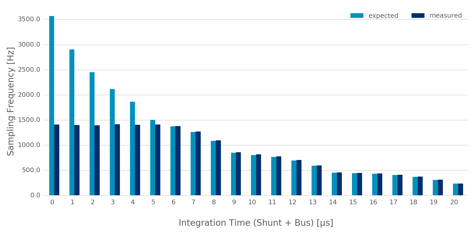
Theoretical vs measured sampling rates
Furthermore, because the transactions are done through a buffer (see next section), if the sampling frequency is too low, the connection may time-out before the buffer is full and ready to be sent. This may be fixed in an upcoming release.
Buffer-based transactions
Samples made available by the INA226 are retrieved by the BBB and stored in a
buffer which is sent back to the host once it is full (see
buffer_samples_count in BaylibreAcmeInstrument.setup for setting its
size). Therefore, the larger the buffer is, the longer it takes to be
transmitted back but the less often it has to be transmitted. To illustrate
this, consider the following graphs showing the time difference between
successive samples in a retrieved signal when the size of the buffer changes:
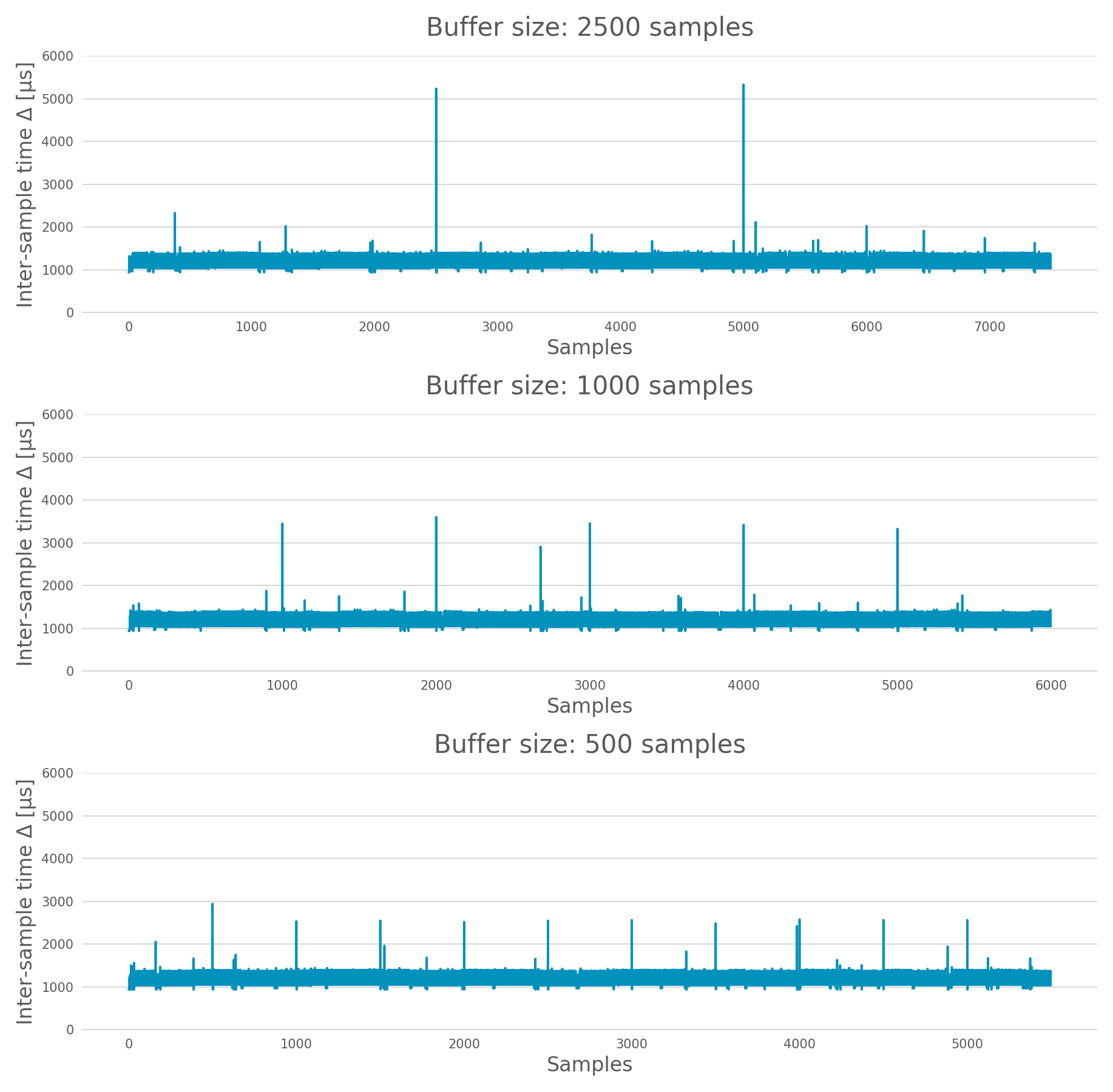
Impact of the buffer size on the sampling regularity
devlib API
ACME Cape + BBB (IIO Context)
devlib provides wrapper classes for all the IIO connections to an IIO context given by libiio (the Linux IIO interface) however only the network-based one has been tested. For the other classes, please refer to the official IIO documentation for the meaning of their constructor parameters.
-
class
devlib.instrument.baylibre_acme.BaylibreAcmeInstrument(target=None, iio_context=None, use_base_iio_context=False, probe_names=None)[source]¶ Base class wrapper for the ACME instrument which itself is a wrapper for the IIO context base class. This class wraps around the passed
iio_context; ifuse_base_iio_contextisTrue,iio_contextis first passed to theiio.Contextbase class (see its documentation for how this parameter is then used), elseiio_contextis expected to be a valid instance ofiio.Context.probe_namesis expected to be a string or list of strings; if passed, the probes in the instance are named according to it in the order in which they are discovered (see previous comment about probe discovery andBaylibreAcmeInstrument.probes). There should be as manyprobe_namesas there are probes connected to the ACME. By default, the probes keep their IIO names.To ensure that the setup is reliable,
devlibrequires minimal versions foriio, the IIO drivers and the ACME BBB SD image.
-
class
devlib.instrument.baylibre_acme.BaylibreAcmeNetworkInstrument(target=None, hostname=None, probe_names=None)[source]¶ Child class of
BaylibreAcmeInstrumentfor Ethernet-based IIO communication. Thehostnameshould be the IP address or network name of the BBB. If it isNone, theIIOD_REMOTEenvironment variable will be used as the hostname. If that environment variable is empty, the server will be discovered using ZeroConf. If that environment variable is not set, a local context is created.
-
class
devlib.instrument.baylibre_acme.BaylibreAcmeXMLInstrument(target=None, xmlfile=None, probe_names=None)[source]¶ Child class of
BaylibreAcmeInstrumentusing the XML backend of the IIO library and building an IIO context from the providedxmlfile(a string giving the path to the file is expected).
-
class
devlib.instrument.baylibre_acme.BaylibreAcmeLocalInstrument(target=None, probe_names=None)[source]¶ Child class of
BaylibreAcmeInstrumentusing the Local IIO backend.
-
BaylibreAcmeInstrument.mode¶ The collection mode for the ACME is
CONTINUOUS.
-
BaylibreAcmeInstrument.setup(shunt_resistor, integration_time_bus, integration_time_shunt, oversampling_ratio, buffer_samples_count=None, buffer_is_circular=False, absolute_timestamps=False, high_resolution=True)[source]¶ The
shunt_resistor(\(R_{shunt}\) [\(\mu\Omega\)]),integration_time_bus(\(T_{bus}\) [s]),integration_time_shunt(\(T_{shunt}\) [s]) andoversampling_ratio(\(N\)) are copied into on-board registers inside of the INA226 to be used as described above. Please note that there exists a limited set of accepted values for these parameters; for the integration times, refer toIIOINA226Instrument.INTEGRATION_TIMES_AVAILABLEand for theoversampling_ratio, refer toIIOINA226Instrument.OVERSAMPLING_RATIOS_AVAILABLE. If all probes share the same value for these attributes, this class providesBaylibreAcmeInstrument.OVERSAMPLING_RATIOS_AVAILABLEandBaylibreAcmeInstrument.INTEGRATION_TIMES_AVAILABLE.The
buffer_samples_countis the size of the IIO buffer expressed in samples; this is independent of the number of active channels! By default, ifbuffer_samples_countis not passed, the IIO buffer of sizeIIOINA226Instrument.sample_rate_hzis created meaning that a buffer transfer happens roughly every second.If
absolute_timestampsisFalse, the first sample from thetimestampschannel is substracted from all the following samples of this channel, effectively making its signal start at 0.high_resolutionis used to enable a mode where power and current are computed offline on the host machine runningdevlib: even if the user asks for power or current channels, they are not enabled in hardware (INA226) and instead the necessary voltage signal(s) are enabled to allow the computation of the desired signals using the FPU of the host (which is very likely to be much more accurate than the fixed-point 16-bit unit of the INA226).A circular buffer can be used by setting
buffer_is_circulartoTrue(directly passed toiio.Buffer).Each one of the arguments of this method can either be a single value which will be used for all probes or a list of values giving the corresponding setting for each probe (in the order of
probe_namespassed to the constructor) with the exception ofabsolute_timestamps(as all signals are resampled onto a common time signal) which, if passed as an array, will beTrueonly if all of its elements areTrue.
-
BaylibreAcmeInstrument.reset(sites=None, kinds=None, channels=None)[source]¶ BaylibreAcmeInstrument.setup()should always be called before calling this method so that the hardware is correctly configured. Once this method has been called,BaylibreAcmeInstrument.setup()can only be called again onceBaylibreAcmeInstrument.teardown()has been called.This method inherits from
Instrument.reset(); calllist_channels()for a list of available channels from a given instance.Please note that the size of the transaction buffer is proportional to the number of active channels (for a fixed
buffer_samples_count). Therefore, limiting the number of active channels allows to limit the required bandwidth.high_resolutioninBaylibreAcmeInstrument.setup()limits the number of active channels to the minimum required.
-
BaylibreAcmeInstrument.start()[source]¶ BaylibreAcmeInstrument.reset()should always be called before calling this method so that the right channels are active,BaylibreAcmeInstrument.stop()should always be called after calling this method and no other method of the object should be called in-between.This method starts the sampling process of the active channels. The samples are stored but are not available until
BaylibreAcmeInstrument.stop()has been called.
-
BaylibreAcmeInstrument.stop()[source]¶ BaylibreAcmeInstrument.start()should always be called before calling this method so that samples are being captured.This method stops the sampling process of the active channels and retrieves and pre-processes the samples. Once this function has been called, the samples are made available through
BaylibreAcmeInstrument.get_data(). Note that it is safe to callBaylibreAcmeInstrument.start()after this method returns but this will discard the data previously acquired.When this method returns, It is guaranteed that the content of at least one IIO buffer will have been captured.
If different sampling frequencies were used for the different probes, the signals are resampled to share the time signal with the highest sampling frequency.
-
BaylibreAcmeInstrument.teardown()[source]¶ This method can be called at any point (unless otherwise specified e.g.
BaylibreAcmeInstrument.start()) to deactive any active probe onceBaylibreAcmeInstrument.reset()has been called. This method does not affect already captured samples.
The following graph gives a summary of the allowed calling sequence(s) where each edge means “can be called directly after”:
![digraph acme_calls {
rankdir = LR
bgcolor = transparent
__init__ -> setup -> reset -> start -> stop -> teardown
teardown:sw -> setup [style=dashed]
teardown -> reset [style=dashed]
stop -> reset [style=dashed]
stop:nw -> start [style=dashed]
reset -> teardown [style=dashed]
}](_images/graphviz-afd85fd53ba6a6e94a0e150764e401b5064a9a52.png)
-
BaylibreAcmeInstrument.get_data(outfile=None)[source]¶ Inherited from
Instrument.get_data(). IfoutfileisNone(default), the samples are returned as a pandas.DataFrame with the channels as columns. Else, it behaves like the parent class, returning aMeasurementCsv.
-
BaylibreAcmeInstrument.add_channel()¶ Should not be used as new channels are discovered through the IIO context.
-
BaylibreAcmeInstrument.list_channels()¶ Inherited from
Instrument.list_channels().
-
BaylibreAcmeInstrument.sample_rate_hz
-
BaylibreAcmeInstrument.OVERSAMPLING_RATIOS_AVAILABLE
-
BaylibreAcmeInstrument.INTEGRATION_TIMES_AVAILABLE¶ These attributes return the corresponding attributes of the probes if they all share the same value (and are therefore provided to avoid reading from a single probe and expecting the others to share this value). They should be used whenever the assumption that all probes share the same value for the accessed attribute is made. For this reason, an exception is raised if it is not the case.
If probes are active (i.e.
BaylibreAcmeInstrument.reset()has been called), only these are read for the value of the attribute (as others have been tagged to be ignored). If not, all probes are used.
-
BaylibreAcmeInstrument.probes¶ Dictionary of
IIOINA226Instrumentinstances representing the probes connected to the ACME. If provided to the constructor, the keys are theprobe_namesthat were passed.
ACME Probes (IIO Devices)
The following class is not supposed to be instantiated by the user code: the
API is provided as the ACME probes can be accessed through the
BaylibreAcmeInstrument.probes attribute.
-
class
devlib.instrument.baylibre_acme.IIOINA226Instrument(iio_device)[source]¶ This class is a wrapper for the
iio.Deviceclass and takes a valid instance asiio_device. It is not supposed to be instantiated by the user and its partial documentation is provided for read-access only.
-
IIOINA226Instrument.shunt_resistor
-
IIOINA226Instrument.sample_rate_hz
-
IIOINA226Instrument.oversampling_ratio
-
IIOINA226Instrument.integration_time_shunt
-
IIOINA226Instrument.integration_time_bus
-
IIOINA226Instrument.OVERSAMPLING_RATIOS_AVAILABLE
-
IIOINA226Instrument.INTEGRATION_TIMES_AVAILABLE¶ These attributes are provided for reference and should not be assigned to but can be used to make the user code more readable, if needed. Please note that, as reading these attributes reads the underlying value from the hardware, they should not be read when the ACME is active i.e when
BaylibreAcmeInstrument.setup()has been called without callingBaylibreAcmeInstrument.teardown().
Examples
The following example shows a basic use of an ACME at IP address
ACME_IP_ADDR with 2 probes connected, capturing all the channels during
(roughly) 10 seconds at a sampling rate of 613 Hz and outputing the
measurements to the CSV file acme.csv:
import time
import devlib

acme = devlib.BaylibreAcmeNetworkInstrument(hostname=ACME_IP_ADDR,
                                            probe_names=['battery', 'usb'])

int_times = acme.INTEGRATION_TIMES_AVAILABLE
ratios    = acme.OVERSAMPLING_RATIOS_AVAILABLE

acme.setup(shunt_resistor=20000,
           integration_time_bus=int_times[1],
           integration_time_shunt=int_times[1],
           oversampling_ratio=ratios[1])

acme.reset()
acme.start()
time.sleep(10)
acme.stop()
acme.get_data('acme.csv')
acme.teardown()
It is common to have different resistances for different probe shunt resistors.
Furthermore, we may want to have different sampling frequencies for different
probes (e.g. if it is known that the USB voltage changes rather slowly).
Finally, it is possible to set the integration times for the bus and shunt
voltages of a same probe to different values. The following call to
BaylibreAcmeInstrument.setup() illustrates these:
acme.setup(shunt_resistor=[20000, 10000],
           integration_time_bus=[int_times[2], int_times[3]],
           integration_time_shunt=[int_times[3], int_times[4]],
           oversampling_ratio=[ratios[0], ratios[1]])

for n, p in acme.probes.iteritems():
   print('{}:'.format(n))
   print('    T_bus = {} s'.format(p.integration_time_bus))
   print('    T_shn = {} s'.format(p.integration_time_shunt))
   print('    N     = {}'.format(p.oversampling_ratio))
   print('    freq  = {} Hz'.format(p.sample_rate_hz))

# Output:
#
#   battery:
#       T_bus = 0.000332 s
#       T_shn = 0.000588 s
#       N     = 1
#       freq  = 1087 Hz
#   usb:
#       T_bus = 0.000588 s
#       T_shn = 0.0011 s
#       N     = 4
#       freq  = 148 Hz
Please keep in mind that calling acme.get_data('acme.csv') after capturing
samples with this setup will output signals with the same sampling frequency
(the highest one among the sampling frequencies) as the signals are resampled
to output a single time signal.
Footnotes
| [1] | There exist different variants of the ACME probe (USB, Jack, shunt resistor) but they all use the same probing hardware (the TI INA226) and don’t differ from the point of view of the software stack (at any level, including devlib, the highest one) |
| [2] | Be careful that in cases where multiple ACME boards are being used, it may be required to manually handle name conflicts |